Evaluation of scorpion body formability by plastic lubrication surface treatment

Copyright © The Korean Society of Marine Engineering
This is an Open Access article distributed under the terms of the Creative Commons Attribution Non-Commercial License (http://creativecommons.org/licenses/by-nc/3.0), which permits unrestricted non-commercial use, distribution, and reproduction in any medium, provided the original work is properly cited.
Abstract
In cold forging, the lubricant relatively plays a role of reducing the processing load because it reduces the friction between the mold and the processing material. As a result, the lubricant improves the processing limit and uniformly deforms the inside of the material, thereby obtaining good metal flow. This study is about an environmentally friendly method of lubricating by applying a film treatment solution to the surface of the target product instead of the conventional phosphate film treatment. In order to develop a one-component lubricant that is performed in one process, a comparative analysis is performed on Single-A (black), Single-B (white), and phosphate film treatment. Single-A and Single-B are single-component lubricants under development, and a friction test was performed using a servo press for comparative analysis with the phosphate film treatment used in the existing field. For the friction test, a double cup friction test, which is a forward and backward extrusion method, was performed and the forward and backward extrusion length ratio was measured. By performing CAE analysis, a graph of the friction factor according to the forward and backward extrusion length ratio could be obtained, and from the result, the friction factor according to each lubrication condition could be obtained. In this study, the friction factor obtained from the test was applied to the scorpion body part, an automobile part, and finally, the formability according to the friction factor was evaluated.
Keywords:
Plastic Lubrication, Double Cup Test, Single-component Lubrication, Scorpion Body1. Introduction
In cold forging, the lubricant relatively plays a role of reducing the processing load because it reduces the friction between the mold and the processing material. The lubricant improves the processing limit, uniformly deforms the inside of the material, and improves the precision of the product by preventing a seizer between the mold and the cut-off. The phosphate film treatment has high lubricity, rust resistance, and improves formability, so it has been widely used as a lubricant for cold forging, extrusion, and plastic processing until now. [1]
Phosphate film treatment, commonly used in cold forging, forms a film through a chemical reaction with a metal surface and forms a strong lubricating film with metal soap that react the emulsifier. However, sludge is generated during the treatment process, causing deterioration, acid waste is generated after washing to pollute the environment, and there is a disadvantage that not only does it require a large space for treatment, but it also takes a lot of time for treatment.[2][3]
Recently, the importance of the environment has emerged in all industries, and in the metal processing industry, the necessity of reducing environmental load and energy reduction technology are urgently required. In addition, because regular replacement of the phosphate treatment tank is required, there are many problems that generate large amounts of waste fluid and waste sludge and increase energy costs.
In order to solve this problem, an attempt was made to develop and apply a water-soluble lubricant, but it is not applied in an actual line due to its low lubrication and friction performance in terms of technology. Therefore, it is required to develop an eco-friendly lubrication treatment device with a simple process treatment to solve the problems of phosphate film treatment.[4]
In general, when a metal is cold-processed, a metal material is coated with a base film, steel is coated with a phosphate film, stainless steel is coated with an oxalate film, and aluminum is coated with a lubrication film. Oil or metal soap is attached when the processing degree is low, and molybdenum disulfide (MoS2) is used when the processing degree is high. Since the base film is formed by a chemical reaction, the treatment process is multi-processed, and management is complicated, and reaction by-products such as iron oxalate and iron oxalate containing phosphoric acid, hydrofluoric acid, etc. and wastewater containing heavy metals are generated. Therefore, there is an urgent need to develop an environmentally responsive lubricant that can reduce industrial waste generation due to the short treatment process and simple management.
One-liquid lubricants are composed of high molecular compounds and inorganic compounds, and they are immersed in a one-liquid lubricant in which the workpiece is diluted and then dried to form a lubricating film. As an alternative to chemical treatment, a review is being promoted, and it has the advantage of significantly reducing the treatment process or waste liquid compared to chemical treatment, so it has been attempted to develop and apply water-soluble lubricants, but it is not applied in the actual line due to difficulties in terms of lubrication and friction performance. Therefore, it is necessary to develop an eco-friendly lubricant that complements the functional aspects of the forging process while solving the problems of phosphate film treatment. In this study, a friction test was performed to evaluate the forging formability of the existing phosphate film and the single-liquid lubricant presented in this study, compared and analyzed through CAE analysis, and the formability was evaluated by applying it to the Scorpion Body, an actual automobile part.
2. Double Cup Friction Test
2.1 The Method of Double Cup Friction Test
The friction test performed in this study was a double-cup test commonly used in cold forging. [5] The materials of punch and workpiece used in this study are SKD11 and SS400 respectively.
The punches were coated TiCN and the specimens were treated phosphate coating as a lubricant considering conventional forming condition. The initial and after deformation shape of workpiece are shown in Figure 1.

The dimensions and shape of double cup test
Servo press model (KOMATU, Japan) was used and the specifications are following, the maximum load capacity is 200Ton, stroke of slide is 250 mm, maximum stroke speed is 40 SPM (strokes per minute). Figure 2 shows the press appearance and die set.

Servo press (SIMPAC) and die set
Figure 3 shows the dimensions of punches. The diameter of punch and counter punch is 14.0mm. This initial diameter and height of the workpiece is 14mm, 32mm respectively.

Dimensions of punches
2.2 Motion of Friction Test
The servo press is used for comparative analysis between the single-component lubricant, which is the subject of development, and the phosphate lubricant used in the field. Since the servo press can control motion, it is intended to evaluate lubrication characteristics using this. The set motion condition is the first mechanical motion forming. Mechanical motion is the same method as a general knuckle press. It is the second pulsing motion forming. Pulsation motion is formed by repeating this method to the forming depth set by the punch, 1 mm rise after 5 mm forming and 1 mm rise after 5 mm forming. The reason for setting the pulsing motion is to check whether the developed single-component lubricant is well buried in the specimen during forming. The third stepwise motion forming is performed. Stepwise motion is formed at 20 SPM by the depth set by punch after 5 mm forming with 2 SPM. The reason for setting the stepwise motion is the same as for setting the pulsing motion. Below, the mechanical motion, pulse motion, and stepwise motion conditions are shown.[6]

The motions of friction tests
2.3 The Result of Double Cup Friction Test
The double cup test was performed according to the servo press motion condition. In order to derive the friction factor according to each lubricant, the measured value of the formed specimen is required. The specimen dimensions for deriving the friction factors are shown in Figure 5. For the measurement of the friction factor, H1 and H2 are measured to obtain H1/H2, and the friction factor is derived by comparing the CAE analysis results of the obtained H1/H2.

The criteria of specimen measurement for deriving friction factor
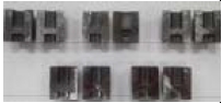
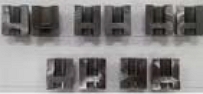
Table 1 shows the shape of specimen after the double cup test according to the press motion condition. After the forward and backward extrusion test, the specimen was cut in 1/2 section to measure the forward length H1 and backward length H2, respectively.

The shape of specimens after the double cup test
Table 2 shows the measured values after the forward and backward extrusion as friction test. The ratio of forward and backward extruded length, that is, the H1/H2 value, was found that the stepwise motion condition was large regardless of the lubricant. The next was mechanical motion, and it was found that the pulsation motion had the lowest extrusion length ratio. In the case of the same motion condition, it was found that lubricant A had the largest extrusion length ratio, followed by lubricant B and had the lowest extrusion length ratio under the phosphate coating condition, which is lubricant C. From the results of the front and rear extrusion test, it can be seen that the metal flow of the one-liquid lubricants A and B is slightly lower than the phosphate film condition. The better the friction characteristics between the die and the material, the smaller the ratio of forward and backward extruded length.
The shape of specimens after the double cup test
3. FE-Simulation for Double Cup Test
3.1 Modeling for FE-simulation
Finite element (FE) simulation is to be performed for the double cup friction test. The analysis was performed under the same conditions as the friction test. The Figure 6 shows the shapes of the punch, die, container and workpiece for analysis. The material is S20C (σ = 484ϵ0.2MPa) and the outer diameter and height are 32mm respectively. There are 50,000 meshes, and the analysis was performed with a 1/4 cross-sectional axisymmetric model considering time consuming.

Modeling for friction test using FE-simulation
The friction factor, m (0 < m <1) was analyzed at 0.02 intervals from 0 to 0.2, and the height of H1/H2 according to the punch stroke was measured. The cross-sectional shapes according to the friction factors are shown in Figure 7 and the ratio of forward and backward extruded length, that is, the H1/H2 value, according to friction factor are shown in Figure 8.

The cross-sectional shapes depend on friction factors

The variation of H1/H2 according to friction factor
Through CAE analysis, it was found that the forward and backward extrusion lengths differ depending on the friction factor. Using the graph in Figure 8, the friction factor for each specimen according to the lubrication conditions was derived as shown in Table 3.
Friction factors according to lubricant conditions
As a result of comparing and analyzing the friction factor of each lubricant according to the servo press motion conditions, it was confirmed that A was 0.11 to 0.13, B was 0.09 to 0.12, and C was 0.08 to 0.10. The existing phosphate coating condition was the lowest, and it was found that it had the lowest friction characteristics in pulsation motion. It was confirmed that the friction factor range of the one-component lubricant (A and B) also had a friction factor in the range of 0.09 to 0.13, and it is judged that it can be applied to cold forging process.
4. Evaluation of Formability for Scorpion Body
4.1 FE simulation for Scorpion Body
This study aims to evaluate the formability of so-called scorpion body parts among automobile parts according to the friction factor. Through the friction test and analysis, it was found that the friction factor, m, according to the types of lubricants A, B, and C ranged from 0.08 to 0.13. Therefore, this study attempted to understand the metal flow characteristics of the scorpion body at equal interval of friction factor as 0.07, 0.09, 0.11, and 0.13. The modeling shape of the scorpion body is shown in Figure 9 below.

Modeling shape of scorpion body
The Figure 9 shows the shapes of the upper punch, lower punch, lower die, lower punch holder and workpiece for analysis. The material is S20C, and the outer diameter and height are 31.3mm, 51.7mm respectively. In order to help understand the shape of scorpion body parts, the metal forming process is shown in Figure 10.

The metal forming process for scorpion body
Figure 11 shows the contact state of the scorpion body part with the punch and die according to the friction factor. In general, in the case of the forward and backward extrusion process, the contact part with the lower die is large, but the contact part with the upper and lower punches is small. This allows good metal flow by reducing the contact part between the tool and the material. However, in the range of friction factors considered in this study, the difference in metal flow characteristics was small, and the contact part with the punch was almost the same.

The contact state for each friction factor
Figures 12 show the distribution of effective stress according to the friction factors, respectively. In case of friction factor was 0.07, the maximum stress was 1,020 MPa, 1,030 MPa in case of 0.09, 1,032 MPa in case of 0.11, and 1,034 MPa in case of 0.13. Naturally, the higher the friction factor, the higher the stress, but there was no significant difference. The maximum stress was found on the side of the upper punch, and the distribution of effective stress was similar regardless of the friction factors.

The effective stress for each friction factor
Figures 13 show the distribution of effective strain according to the friction factors, respectively. In case of friction factor was 0.07, the maximum stain was 4.52, 4.75 in case of 0.09, 4.79 in case of 0.11, and 4.81 in case of 0.13. The higher the friction factor, the higher the stain, but there was no significant difference. The maximum strain was also found on the side of the upper punch, and the distribution of effective strain was similar regardless of the friction factors.

The effective strain for each friction factor
After FE-simulations, the forward and backward extruded lengths were measured according to the friction factors. As a result, it was confirmed that forward and backward extruded lengths relatively decreased as the friction factor increased. The smaller the friction factor, the lower the metal flow resistance to the upper and lower parts, so the metal flow to the upper and lower parts increases.

The forward and backward extruded lengths in FE simulations according to friction factors
As the friction factor increases, of course, the forming load increases. Figure 15 shows the forming load for the lowest and largest cases. In the case of 0.07, the lowest friction factor considered in this study, a forming load of 264 tons, and in the case of 0.13, the forming load was 282 tons. There is a load difference of about 18 tons.

The forming load of scorpion body in FE simulation
4.2 The Comparison of FE simulation and Experiment for Scorpion Body
In this study, a cold forging test of the scorpion body was performed by applying a type B lubricant. Type B lubricant was applied instead of the existing phosphate coating under the same conditions for the shape of the initial material and the shape of the punch and die. Figure 16(a) shows the test process and the final scorpion shape is shown in Figure 16(b). A scratch occurred on the die contact, but no defect occurred in the shape of the part.

The forming test of scorpion body
As a result of the previous double cup friction test, the average friction factor, m of the type B lubricant is about 0.1. Therefore, in this study, the results are shown in Figure 17 by comparing the experimental results applying the type B lubricant with the FE-simulation results applying the friction factor m=0.1. The test and analysis results were judged to be almost identical to each other and did not show any defects such as un-filling cavity, folding etc. As a result of this study, it was found that the type B one-component lubricant can be used for actual cold forging process. One-component lubricant has a great advantage in simplifying the process as well as environmental friendliness. However, in order to confirm the safety of high-speed cold forging, mass production tests should be performed and results on the wear resistance of the mold should be presented.

Comparison of FE simulation and test shape of scorpion body
4. Conclusion
In this study, in order to determine the applicability of an eco-friendly lubricant to the field instead of the existing phosphate coating, a friction test of a one-component lubricant was performed and applied to the automobile part scorpion body through CAE analysis. The friction characteristics according to various servo press motions were analyzed through a double cup friction test, and as a result, it was confirmed that the one-component lubricant is useful. In addition, a quantitative friction constant value was derived based on the friction test and analysis for the same conditions, and the validity of the analysis result was confirmed by comparing the analysis and experimental results by applying it to the automobile part scorpion body as a one-component lubrication condition. From this study, the applicability of one-component lubricant to the cold forging process was confirmed. However, for actual mass production application, test analysis of the continuous forming conditions of one-component lubricant is required, and additional studies on the tool life and wear characteristics are considered necessary.
Acknowledgments
This work was supported by Changshin University Research Fund of 2025-002.
Author Contributions
Conceptualization, D. Kim; Methodology, D. Kim; Software, D. Kim; Validation, D. Kim; Formal Analysis, D. Kim; Investigation, D. Kim; Resources, D. Kim; Data Curation, D. Kim; Writing—Original Draft Preparation, D. Kim; Writing—Review & Editing, D. Kim; Visualization, D. Kim; Supervision, D. Kim; Project Administration, D. Kim; Funding Acquisition, D. Kim.
References
-
K. Kitamura, “A Study on The Forging and Lubrication,” Transactions of Materials Processing, vol. 15, no. 6, 2006 (in Korean).
[https://doi.org/10.5228/KSPP.2006.15.6.407]

- M. S. Lee, C. T. Cheong, G. H. Lee, J.H. Kim, G. D. Lee, S. S. Hong, "A Study on Low Temperature Phosphating for Clod Forming," J. of the Korean Institute of Surface Engineering, vol. 35, no. 5, pp. 279-288, 2002 (in Korean).
- J. H. Kim, W. J. Song, S. W. Kim, “Acoustic emission Signals Monitoring in the Friction Test of Phosphate-coated Steel for Cold Forging,” Proceedings of the KSAE Conference, p. 1051, 2023 (in Korean).
- I. S. Lee, J. S. Je, Y. R. Kim, B. M. Kim, “Optimization of Coating Process of Water-based Lubricant for Cold Forging,” Transactions of Materials Processing, vol.16, no. 7, pp. 486-489, 2006 (in Korean).
- J. H. Kim, B. H. Ko, T. K. Lee, B. M. Kim, “Evaluation and Application of Friction Characteristics in Deformation Type,” Proceedings of the KSTP Conference, p. 75, 2016 (in Korean).
- D. H. Kim, M. C. Park, “A Study on the Friction Characteristics of H-cup in Lubricants for Cold Forging,” Proceedings of the KSMTE Conference, p. 328, 2022 (in Korean).