Onboard trial application of a Damage Control Support System (DCSS) prototype for low-carbon and autonomous vessels

Copyright © The Korean Society of Marine Engineering
This is an Open Access article distributed under the terms of the Creative Commons Attribution Non-Commercial License (http://creativecommons.org/licenses/by-nc/3.0), which permits unrestricted non-commercial use, distribution, and reproduction in any medium, provided the original work is properly cited.
Abstract
The increasing adoption of high-risk alternative fuels (e.g., methanol, ammonia) and large-scale battery/fuel cell systems necessitates enhanced onboard damage control solutions. Simultaneously, the evolution toward Maritime Autonomous Surface Ships (MASS) reduces available crew capacity for emergency responses. To address these challenges, this study developed a new Damage Control Support System (DCSS), which simplifies and visualizes previously complex procedures using intuitive interfaces. The system was installed and tested on a 1MW-class Green Test Bed (K-GTB) vessel. The DCSS includes a scenario-based response engine with thousands of fire and flooding scenarios per vessel, intuitive operational protocols using ISO 23120-compliant coded graphic symbols, and a real-time decision-support loop based on more than 30 integrated sensors. The full system was deployed on a 2,600 GT-class K-GTB vessel, fully integrated with the propulsion and engine control system and supported by a subordinate Buoyancy Support System. It demonstrated real-time emergency handling capabilities under harsh marine conditions. This paper presents the DCSS design framework, technological challenges during implementation, verification strategies, and implications for international standardization.
Keywords:
Damage control, Autonomous ship, Alternative fuel, Emergency response, Buoyancy support, Graphic symbol1. Introduction
The shift toward decarbonization in maritime industries has been actively propelled by the IMO Initial Strategy on Reduction of GHG Emissions (MEPC.304(72)), leading to the accelerated adoption of alternative fuel systems such as methanol, ammonia, hydrogen fuel cells, and large-scale batteries [1]. However, these systems inherently raise the operational complexity and safety risks of shipboard environments due to their high flammability, toxicity, and failure propagation characteristics, particularly when operated by crew unfamiliar with such technologies. These challenges significantly increase the risk of onboard accidents and complicate emergency response efforts. At the same time, the transition to Maritime Autonomous Surface Ships (MASS) may lead to a shortage of trained personnel capable of responding to emergencies up to Degree 2, and from Degree 3 onwards, remote or automated casualty response becomes necessary, thereby further reinforcing the urgent need for damage control systems designed with these requirements in mind [2].
Although existing Damage Control Systems (DCS) in naval vessels (e.g., L3Harris IPMS and Martec DCS) and large passenger ships offer high levels of functionality, operational feedback has highlighted key limitations such as high cost, complex multi-layered interfaces, and the need to simulate and calculate damage stability in real time under emergency conditions [3][4]. These factors make them ill-suited for application on small- and medium-sized commercial vessels. Moreover, most legacy systems were not designed with remote control, autonomous operation, or integration with digital twin technologies in mind—capabilities that are essential for vessels adopting new fuels and propulsion systems under reduced-crewing or remote-control regimes.
To address these issues, this study proposes a new Damage Control Support System (DCSS), designed for intuitive and rapid operation while remaining compliant with emerging international standards such as ISO 23120:2021 [5].
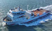
The proposed DCSS was implemented on Korea’s 1 MW-class Green Test Bed (K-GTB) vessel, which is a hybrid demonstrator vessel with a propulsion capacity of 2.2 MW, capable of validating MW-class batteries, fuel cells, and dual-fuel engines as described in Table 1.

Specifications of the K-GTB vessel
2. Design and Architecture of DCSS
The DCSS is structured based on the framework by Kang et al. (2011), consisting of a graphical user interface (GUI), sensor interface modules, and a scenario-based simulation database for flooding and fire emergencies [6]. The DCSS architecture is organized into two major subsystems: the Emergency Response System (ERS) and the Buoyancy Support System (BSS). The ERS is capable of supplying emergency power through emergency generators and Uninterruptible Power Supply (UPS) even during casualty conditions, and it manages sequential damage response in compliance with regulations. Flooding simulations were designed under assumptions such as hull breach due to collision or grounding, incorporating wave height, wave direction, and period data along with compressible airflow modeling. Thousands of flooding scenario cases were generated and encoded into the DCSS database. Upon detection of an incident, the system presents analogous historical scenarios on the UI.
DCSS guiding operators through predefined emergency response procedures in compliance with regulatory protocols. In the case of a flooding event, the system evaluates flooding propagation pathways and changing behaviors.

Graphical user interface for flooding damage response

Dynamic ship motion analysis displayed in DCSS GUI
The damage behavior of the compromised vessel was analyzed using KRISO's in-house simulation tool, SURVSHIP, which was previously employed in earlier versions of SMTP [7].
The core methodology is based on the Dynamic Orifice Flow Model, wherein the inflow rate of seawater through the damage opening varies over time and cannot be adequately described by static hydrostatic assumptions [7]. Instead, it incorporates unsteady, compressible, and turbulent flow characteristics. The governing equation is defined as:
Components of the DCSS including the ERS and the BSS
| (1) |
Where:
Q(t): Inflow rate at time t
Cd: Discharge coefficient (typically 0.6–0.8)
A(t): Orifice cross-sectional area, which may vary with submergence depth and time
ΔP(t): Pressure difference across the opening
ρ: Fluid density (approximately 1025 kg/m³ for seawater)
Unlike conventional models, Lee et al. (2014) incorporated a compressible air cushion effect, whereby rising internal pressure inside the compartment due to water ingress leads to a gradual decrease in inflow rate [8]. This phenomenon is captured by air compression within the compartment, using the ideal gas law:
| (2) |
Where:
P(t): Internal air pressure in the compartment at time t
V(t): Remaining air volume in the compartment at time t
n: Number of moles of trapped air (assumed constant)
R: Universal gas constant (8.314 J/mol·K)
T: Absolute temperature of the trapped air (Kelvin), often assumed constant under isothermal conditions
By solving for (𝑡), the simulation quantifies the effect of rising internal air pressure in reducing water ingress velocity.
When substantial air remains in the compartment or when upper openings are sealed, the inflow rate is initially rapid but drops sharply over time due to pressure buildup. Lee et al. (2015) numerically reproduced this “initial surge followed by damping” pattern through simulation. As water accumulates through the damaged section, both the vessel’s center of gravity (CG) and center of buoyancy (CB) shift, leading to changes in the ship’s metacentric height (GM). The GM is computed as:
| (3) |
GM: Metacentric height (indicator of ship stability)
KB: Vertical distance from keel to center of buoyancy
BM=I/Δ: Transverse metacentric radius (second moment of area divided by displacement)
KG: Vertical distance from keel to center of gravity
If 𝐺𝑀 < 0, the vessel loses its inherent stability and may experience heeling or capsizing.
Therefore, accurate prediction of GM is one of the most critical elements in systems like DCSS (Damage Control Support System).

Graphical interface for fire scenario-based emergency response [16]
These models form the foundational basis for constructing the flooding scenario database used in DCSS development and are key in designing scenario-specific emergency response protocols. The DCSS incorporates simulations for all compartments where damage might occur, calculating air volume changes (air cushion effect) and the resulting air pressure rise and inflow reduction. Based on these results, real-time updates of KB, BM, and KG are performed to dynamically calculate GM and assess whether stability thresholds (i.e., GM < 0) are exceeded. The outcomes are visualized through compartment-specific diagrams showing breach locations and time-dependent ship motion. This enables DCSS operators to quickly and intuitively assess ship behavior and stability for specific incidents using a prebuilt scenario-response database.
In fire events, compartment-specific fire grades are preassigned. When a fire is verified via multiple sensors (e.g., heat, smoke, and CCTV), the system retrieves relevant smoke and heat propagation patterns from the scenario database, enacts HVAC and opening controls, and initiates either onboard or remote fire suppression actions. For fire events, full ship-scale simulations were conducted using the U.S. NIST's Fire Dynamics Simulator (FDS).
To support time-critical decisions and evacuation planning, Available Safe Egress Time (ASET) thresholds were incorporated into the scenario simulations. Smoke spread time was calculated based on a 1.8-meter breathing height threshold. Thermal exposure was limited to below 60°C for crew survivability. Toxic gas criteria included carbon monoxide concentrations up to 1,400 ppm, carbon dioxide up to 5%, and oxygen levels maintained above 15% [9]. Minimum visibility limits were set to 10 meters. These parameters were used in compartment-specific simulations and encoded into the response database to ensure safe and compliant evacuation guidance. Evacuation analysis was conducted using FDS, developed by the U.S. National Institute of Standards and Technology (NIST). Figure 4 shows a full-ship scale model of the K-GTB, in which fire scenarios were assumed in areas such as the bridge, engine room, battery compartment, and fuel cell space, with designated fire sources for simulation. This fire simulation enables the assessment of smoke and heat propagation patterns and can be utilized to establish evacuation routes and response strategies for actual fire incidents.

Examples of fire scenario based simulation outputs
Although the model does not incorporate building-specific facilities such as escalators, elevators, or automatic doors, this limitation is inconsequential for ship-based simulations, as such facilities are not present on the K-GTB platform.
The evacuation simulation followed the guidelines set by IMO MSC.1/Circ.1533 and the methodology described by Jin Choi et al. (2010) [9][10]. Accordingly, distinct occupancy scenarios were modeled for daytime and nighttime. During the day, crew members were assumed to be distributed across common and service areas (excluding residential zones), whereas at night, 1/3 of the occupants were assigned to public/service areas and 2/3 to their respective sleeping quarters. Final evacuation time was defined as the moment when the last individual exited to an openair deck. The designated evacuation points varied by deck: personnel located on the bridge or main deck were assumed to evacuate to the lifeboats installed shelter deck on the main deck, while those on lower decks were routed to the shelter deck or the aft open deck. Given that K-GTB is crewed by personnel trained in emergency procedures, the minimum reaction time for crew members was set at 30 seconds. For accompanying researchers onboard, response times were randomly distributed between 30 and 300 seconds to reflect variable recognition and decision-making behavior.
The BSS, in accordance with Kang et al. (2018), is activated when vessel stability is compromised due to flooding [11]. It deploys inflatable buoyancy chambers using either carbon dioxide (CO2) or ambient air as a supply source, governed by motorized control valves and pressure-temperature regulators. Monitoring is achieved through pressure feedback integrated with a vaporizer. All system components were designed with reference to ISO 23121-1 and ISO 23121-2, and, as formal type approval criteria have not yet been established, their functions and configurations were verified through third-party inspection by an accredited organization [12].

GUI interface for operating the BSS

Installation layout of buoyancy chambers on K-GTB
To ensure survivability in severe damage scenarios, the buoyancy chambers were designed to provide residual buoyancy even in cases where two or more adjacent compartments are flooded simultaneously, exceeding the minimum subdivision standards prescribed by SOLAS [13].
This configuration is intended to prevent total sinking and to secure critical time for evacuation and emergency response. On the K-GTB demonstrator, buoyancy chambers were installed in the forward bow thruster room and the engine room. In the engine room, the chambers were modularized into multiple units to account for compartment permeability and spatial constraints. Furthermore, to prevent mechanical damage to the chambers during deployment—particularly from sharp edges or internal structural components—protective guide panels were installed at potential contact points within the compartment.
The HMI is designed using ISO 23120 compliant graphic symbols, enabling intuitive identification and response tracking [14].
Codified symbol sets allow real-time remote monitoring and operational control. By replacing traditional manual input methods with predefined scenarios and visual interfaces, DCSS streamlines tasks such as damage stability calculations and fire propagation assessments. This graphical interaction framework is enhanced with shortcut keys proposed by Kang et al. (2021), improving both usability and situational response efficiency [15].
3. Implementation on K-GTB
To verify the practical utility of the developed DCSS, onboard installation and operational validation were essential. While legacy damage control systems are typically integrated as submodules within engine control systems (ECS) in naval or passenger vessels, retrofitting such systems for validation is often constrained by the difficulty of signal-level interfacing with pre-existing ECS frameworks. To overcome this, the Korea Greenship Test Bed (K-GTB), a 2,600 GT-class seagoing demonstrator developed by KRISO, was selected for full-scale DCSS deployment and testing.
The K-GTB’s ECS features an open-signal architecture that allows seamless integration with subsystems such as DCSS. This open configuration enables flexible sensor mapping, subsystem interoperability, and effective monitoring under operational conditions. A prototype DCSS logic processor was installed in the aft bridge console of the K-GTB and connected to the ECS via hardwired and wireless protocols. The DCSS prototype receives input from over 30 analog and digital sensor nodes.
The network infrastructure adopts a hybrid wired-wireless communication topology based on MODBUS/TCP and CAN protocols. Redundant communication paths are incorporated to ensure continued functionality in degraded modes.
The DCSS interfaces with key ECS and sensor variables such as temperature, smoke, water ingress, power loss, and ventilation state. Fault tree and event tree models were constructed to represent accident scenarios, including hydrogen/ammonia leak ignition, battery thermal runaway, and hull breaches.
The visualizes real-time sensor inputs and emergency states using ISO 23120-compliant graphic symbology. In contrast to legacy alarm and monitoring systems that merely report anomalies, DCSS provides integrated workflows for incident detection, onboard response, external alerting, and follow-up actions. This enables comprehensive and consistent incident management both onboard and remotely.
4. Onboard Trial and Evaluation
To verify the performance and operational feasibility of the developed DCSS and BSS under real-world conditions, a series of onboard sea trials and commissioning tests were conducted using the K-GTB vessel.
For the Damage Control Support System (DCSS), a 9-day operational trial was carried out to evaluate system functionality and the applicability of scenario-based response protocols. Throughout the trials, real-time data inputs from various onboard sensors (e.g., flooding, smoke, temperature) were successfully integrated into the logic processor, and scenario-triggered emergency responses were executed without delay. Any minor software or logic inconsistencies discovered during the trials were promptly corrected, and the insulation resistance performance of all hardware components was improved to meet regulatory standards. In addition, an English-language Emergency Response Procedure Manual was compiled to support crew training on DCSS operations. In parallel, the Buoyancy Support System (BSS) underwent a dedicated trial in February 2025 to validate subsystem integrity and responsiveness in the installed configuration.
The tests focused on verifying the performance of key components, including flooding sensors, temperature and pressure sensors, motor-driven valves, vaporizer interface, CO₂ supply pressure, and the inflation of buoyancy cells. Data interfacing and functional responsiveness were evaluated in coordination with the DCSS framework, and automated BSS activation was successfully demonstrated under flooding scenarios as part of the integrated trial.
Figure 7 shows the DCSS installed on the K-GTB during demonstration operations, mounted on a dedicated console in the aft bridge and integrated with onboard sensors.

Onboard test and demonstration of DCSS
5. Discussion and Future Work
The initial prototype of the DCSS successfully passed on-land basis third-party certification by accredited testing agencies for both ERS and BSS. Following its installation on the K-GTB, the system has been under field trials and has received positive feedback for being significantly more intuitive and user-friendly for onboard personnel compared to conventional DCS platforms.
However, the currently deployed DCSS still requires the capability to automatically infer flooding locations without manual input. This would involve real-time estimation of damage scenarios based on changes in ship behavior and sensor feedback. To enable this, advanced AI technologies are needed to identify simulation scenarios that closely match real-world incidents.
In this regard, time-series similarity metrics such as Dynamic Time Warping (DTW) can be employed to analyze variations in heel angle or inflow rates. Furthermore, scenario retrieval from the simulation database may leverage K-Nearest Neighbors (K-NN) or Faiss-based approximate nearest neighbor search algorithms. For deeper integration of physical ship behavior, Physics-informed Neural Networks (PINN) are also being considered.
The research team is planning to enhance damage estimation capabilities by incorporating wave data acquired from wave radars and correlating it with ship motion information. By using sensor data (flooding sensors, inclinometers, and wave radar), feature embedding can be conducted, followed by similarity-based retrieval using KNN or ANN models. This would enable the system to estimate the flooding location, breach size, and progression over time and to retrieve the most relevant simulation cases [15].
To facilitate the deployment and global adoption of DCSS, international cooperation is underway. In parallel, technical documentation was submitted to the IMO in the form of MSC 109/INF.15 (2024) to present the developed technologies and propose international joint research and collaboration [17].
7. Conclusion
This study demonstrated the feasibility and operational benefits of the DCSS tailored for next-generation low-carbon and autonomous vessels. By integrating scenario-based emergency logic, ISO-compliant visual interfaces, and real-time sensor fusion, the DCSS effectively supports rapid, informed decision-making under fire and flooding accidents. Full-scale deployment aboard the 2,600 GT K-GTB demonstrator validated both the ERS and BSS under onboard conditions. While the current system shows high usability and performance, further advancements are underway to enable AI-based inference of flooding scenarios using time-series similarity, feature embedding, and physics-informed models. These results contribute not only to improving maritime safety but also to enhancing resilience and autonomy in the context of decarbonized shipping.
Acknowledgments
This work was supported by the Ministry of Oceans and Fisheries of Korea through the National R&D Projects 2050000738 (PMS6470) and 1525014739 (PMS6572). The authors would like to express their sincere gratitude to Marine Tech-In Co., Ltd. for their participation and support in this study.
Author Contributions
Conceptualization, H. J. Kang; Methodology, H. J. Kang; Software, K. K. Lee; Formal Analysis, H. J. Kang and K. K. Lee; Investigation, H. J. Kang and K. K. Lee; Resources, H. J. Kang and K. K. Lee; Data Curation H. J. Kang and K. K. Lee; Writing-Original Draft Preparation, K. K. Lee; Writing-Review & Editing, H. J. Kang; Visualization, H. J. Kang and K. K. Lee; Supervision, H. J. Kang; Project Administration, H. J. Kang; Funding Acquisition, H. J. Kang.
References
- International Maritime Organization, Initial IMO Strategy on Reduction of GHG Emissions from Ships, MEPC.304(72), 2018.
- International Maritime Organization, Consideration of the Report of the Maritime Safety Committee, MSC.1/Circ.1604, 2020.
- L3Harris MAPPS, Integrated Platform Management System (IPMS) [Online]. Available: https://defense.info/wp-content/uploads/2020/01/L3M_DS_IPMS_011117i.pdf, , Accessed August 1, 2025.
- Martec Ltd., Decision Support System for Shipboard Emergencies, Technical Datasheet, 2019.
- International Organization for Standardization, ISO 23120:2021 Ships and Marine Technology – Damage Control Information for the Crew, Geneva, Switzerland: ISO, 2021.
-
H. J. Kang, J. G. Shin, and J. K. Lee, “A business model-based design of a damage control support system for naval ships,” Systems Engineering, vol. 15, no. 1, pp. 14-27, 2012.
[https://doi.org/10.1002/sys.20191]

-
G. J. Lee, “Dynamic orifice flow model and compartment models for flooding simulation of a damaged ship,” Ocean Engineering, vol. 109, pp. 635–653, 2015.
[https://doi.org/10.1016/j.oceaneng.2015.09.051]
-
G. J. Lee, “Self similarity in the equation of motion of a ship,” International Journal of Naval Architecture and Ocean Engineering, vol. 6, pp. 333–346, 2014.
[https://doi.org/10.2478/IJNAOE-2013-0183]
- International Maritime Organization, Guidelines for evacuation analysis for new and existing passenger ships, MSC.1/Circ.1533, 2016.
-
J. Choi, S. Y. Kim, S. C. Shin, H. J. Kang, and B. J. Park “Development of an evacuation time calculation program for passenger ships based on IMO Guidelines, MSC. 1/Circ. 1238,” Journal of the Society of Naval Architects of Korea, vol. 47, no. 5, pp. 719-724, 2010.
[https://doi.org/10.3744/SNAK.2010.47.5.719]
-
H. J. Kang, I. Kim, J. Choi, G. J. Lee, and B. J. Park, “A concept study for the buoyancy support system based on the fixed fire-fighting system for damaged ships,” Ocean Engineering, vol. 155, pp. 361–370, 2018.
[https://doi.org/10.1016/j.oceaneng.2018.02.040]
- International Organization for Standardization, ISO 23121 1:2019 & ISO 23121 2:2019 Ships and marine technology — Inflatable Buoyancy Support Systems Against Flooding of Ships, Geneva, Switzerland: ISO, 2019.
- International Maritime Organization, International Convention for the Safety of Life at Sea (SOLAS), Consolidated Edition, 2020.
- International Organization for Standardization, ISO 23120:2021, Geneva, Switzerland: ISO, 2021.
-
H. J. Kang, J. Choi, and D. Lee, “Coded shortcut key basis rapid plotting for onboard emergency responses,” Marine Technology Society Journal, vol. 55, no. 1, pp. 73–87, 2021.
[https://doi.org/10.4031/MTSJ.55.1.8]
-
Z. Li, D. Yang, and G. Yin, “Ship flooding time prediction based on composite neural network,” Journal of Marine Science and Engineering, vol. 11, no. 6, 1123, 2023.
[https://doi.org/10.3390/jmse11061123]
- Republic of Korea, Damage Control System for Autonomous Ships: Submission to IMO MSC 106, MSC 106/5/2 and INF.15, 2022.