
Process design of net shape cold forging for HEV pinion gears

Copyright © The Korean Society of Marine Engineering
This is an Open Access article distributed under the terms of the Creative Commons Attribution Non-Commercial License (http://creativecommons.org/licenses/by-nc/3.0), which permits unrestricted non-commercial use, distribution, and reproduction in any medium, provided the original work is properly cited.
Abstract
Under the global imperative of carbon neutrality, the automotive industry is undergoing a rapid paradigm shift from internal combustion engines to electric and hybrid electric vehicles (HEVs). In the hybrid mid-to-large SUV market, where high energy efficiency and robust driving performance are simultaneously demanded, the differential gear system has become increasingly critical. Specifically, the pinion gear—which transmits power from the drive shaft to the ring gear—is subjected to severe shock loads and cyclic fatigue due to the heavy curb weight of SUVs and the alternating inputs of high engine output and instantaneous electric motor torque. Concurrently, precise tooth profile and backlash management are required for NVH refinement. To achieve cost reduction and high-volume production, this study proposes a near-net shape cold forging process design that streamlines the conventional sequence (upsetting, forging, piercing, and trimming) into an optimized three-stage process (upsetting, forging, and piercing). Using Computer-Aided Engineering (CAE) simulations, this research evaluates critical process parameters to validate the feasibility of the developed manufacturing process.
Keywords:
Hybrid SUV, Differential pinion gear, Near-net shape, Cold forging, CAE simulation1. Introduction
The modern automotive industry is undergoing a rapid paradigm shift in power trains, transitioning from traditional internal combustion engines to electric vehicles (EVs) and hybrid electric vehicles (HEVs). Amidst these changes, the hybrid mid-to-large SUV market concurrently demands both exceptional energy efficiency and robust driving performance. Consequently, ensuring the reliability and performance of the differential gear has become more critical than ever. [1]-[3] The differential gear is an essential device that enables smooth cornering by allowing the left and right wheels to rotate at different speeds when the vehicle navigates curved roads. Among its components, the pinion gear serves as a vital bridge in the drive train, transmitting the power delivered from the drive shaft to the ring gear. [4][5]
Conventional manufacturing methods for pinion gears have typically relied on a sequential four-stage process consisting of upsetting, forging, piercing, and trimming. However, this traditional approach suffers from structural disadvantages, including increased unit costs due to the redundant operation of multiple press machines, limitations in production speed, and reduced quality and escalating die costs caused by the severe wear of trimming dies.
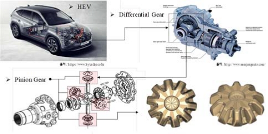
Current application and shape of pinion for hybrid SUV medium- and large-sized automatic devices
To respond to surging market demands and secure global cost competitiveness, the automotive parts manufacturing industry is currently dedicating concerted efforts toward developing near-net shape forming technologies that minimize material loss, as well as process-reduction technologies aimed at maximizing production efficiency. A combined forging-trimming process presents a highly challenging technical hurdle with scarcely any global precedents.
Furthermore, implementing a cold forging method induces work hardening effects and secures continuous metal flow lines (grain flow). This offers a powerful advantage by significantly enhancing fatigue strength and tooth surface durability compared to conventional machined parts, thereby minimizing the risk of failure under high-torque driving conditions.
Accordingly, this study proposes a near-net shape cold forging process design that streamlines the conventional four-stage process into a three-stage system—comprising upsetting, combined forging-trimming, and piercing—to optimize the production framework of pinion gears for hybrid mid-to-large SUV differentials. To realize this, commercial finite element analysis (CAE) software was utilized to precisely evaluate the forming load, metal flow characteristics, and stress-strain distributions for each stage. In particular, process variables for upsetting (height, h), which dictates the precise seating of the material within the die, and near-net shape cold forging variables such as clearance, corner R, which directly influence tooth profile filling, were established, and analyses were conducted based on an orthogonal array. Furthermore, an ANN(Artificial Neural Network) was introduced to efficiently interpret data and derive optimal conditions for unlearned parameters, thereby establishing the optimal combination of die and process variables. [6][7] Finally, based on the optimized design, a production-ready die and a 3-axis automated transfer line are to be constructed. The validity and mass-production feasibility of the proposed near-net shape cold forging process design will be verified through prototype manufacturing and reliability evaluations scheduled to be conducted by an officially certified testing agency.
2. Process Analysis and Design
2.1 Analysis of the Conventional Manufacturing Process
The conventional mass-production line for pinion gears suffered from structural limitations, as it sequentially performed the forming process utilizing two separate machines: a forging press and a trimming press. The specific stages of the conventional process followed a four-step sequence (OP10 to OP40) as detailed below:
① OP10 (Upsetting Stage): This stage involves compressing the cut cylindrical raw material billet in the axial direction to expand its diameter, thereby establishing the initial geometry of the preform to guarantee the final tooth profile formability.
② OP20 (Forging Stage): This is the primary forging process where the material is forced to flow into the upper and lower die cavities to shape the complex bevel tooth profile characteristic of pinion gears, along with the boss structure for drive shaft connection.
③ OP30 (Piercing Stage): This shearing operation involves lowering a punch to pierce a central through-hole in the core of the pinion gear, allowing a power transmission shaft, such as a drive shaft, to pass through and connect.
④ OP40 (Trimming Stage): This final separation process shears and removes the unnecessary burrs and flash formed by the material extruding outside the parting line of the upper and lower dies during the OP20 forging compression phase, using a dedicated trimming press and die set.
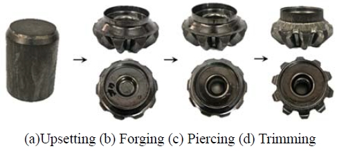
The conventional sequence for pinion gear of SUV
This conventional four-stage layout induces critical problems in terms of equipment load and line efficiency. First, because the seamless synchronization of two physically separated press units is indispensable, the total cycle time is prolonged to approximately 14 seconds per piece, which severely hinders the realization of high mass productivity. Second, due to the nature of the standalone trimming operation, extreme shear stress concentration and wear are heavily localized on the internal corners and cutting edges of the trimming die. Consequently, it has been consistently reported that the actual lifespan of the die deteriorates to under 100,000 strokes, failing to reach its designated design life of 200,000 strokes. This has been analyzed as the primary factor causing frequent line shutdowns, escalating die maintenance costs and non-uniformity in the geometric accuracy of the gear tooth profile.
2.2 Integrated Process Design
In this study, to meet the annual supply demand for hybrid mid-to-large SUVs and to drastically secure quality stability, a streamlined three-stage process was designed to integrate and execute the conventional OP20 forging and OP40 trimming steps within a single-stage press machine. The specific stage-by-stage forming concepts of the newly devised near-net shape-based three-stage forging process design are as follows:
① Improved Stage 1 (Upsetting): This stage involves compressing and deforming the supplied initial raw material billet to form the preform. The critical aspect here is ensuring perfect positioning without any physical misalignment when seating the preform into the die cavity of the subsequent second stage, while simultaneously performing optimized initial volume distribution to allow a seamless material flow up to the edges of the gear tooth profile. To minimize material loss and achieve a near-net shape, the geometric dimensions of the raw material billet were derived and matched to a specification of Ø29.3 × h32.5 with an initial total weight of 172 g.
② Improved Stage 2 (Combined Forging + Trimming Process): This is the core innovative phase of the proposed manufacturing technology. As the pressing punch descends to perform impression forging of the gear tooth profile and the boss, high-strength specialized cutting edges are densely arranged within the internal die structure. This design induces the simultaneous and real-time shear separation of the flash line precisely when the forging load reaches its peak, thereby completely eliminating the conventional standalone trimming press equipment and its independent process stage. Furthermore, by applying this integrated die mechanism, the flash discharge geometry was significantly downsized compared to conventional machining allowances, deriving a near-net shape modification design that directly reduces the weight of the part itself by approximately 7g.
③ Improved Stage 3 (Piercing): This final finishing stage pierces the central through-hole immediately after the combined forming and trimming process is completed. Since this process induces only localized shearing on a part where the tooth profile forming is already finished, it generates an exceptionally low forming load, making it highly advantageous for independent layout arrangement.
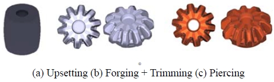
Integrated process design for pinion gear of SUV
3. FE simulation for Pinion Gear
3.1 Integrated Process Design for Pinion Gear
In this study, in order to minimize the weight, we intend to design a semi-finished cold forging shape in consideration of the shape and dimensions of the final processed product. In addition, in order to develop a three-step molding method by deleting the trimming process from the existing process, the final shape modification is inevitable. In addition, in order to minimize material loss and machining, the design modification of the tooth and the boss part is required, and it is very important to design so that molding defects do not occur. Figure 4 shows the modified final pinion gear shape. The material used in this study is with an initial material specification of Φ29.3 mm × 32.5 mm and a weight of 172 g. The friction conditions at the site are controlled by applying A.S.B (softening, shortening, phosphate film lubrication) treatment before upsetting. In the analysis of this study, m 0.12 was applied, taking into account the general friction characteristics. [8]
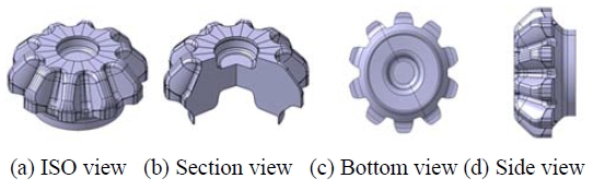
Modified shape for pinion gear
3.2 Upsetting Process
Improved Stage 1, the upsetting step, requires highly rigorous control of process variables because it must form a preform with an optimal geometry that can be accurately and physically seated within the subsequent combined cold forging die cavity without any eccentricity. In this study, the clear distance height between the holder and the die operating inside the upsetting tool set was designated as the primary design variable, and plastic deformation finite element analysis (FEA) was performed utilizing the commercial non-linear simulation software, AFDEX. The upsetting process and its corresponding design variable are illustrated in Figure 5(a).
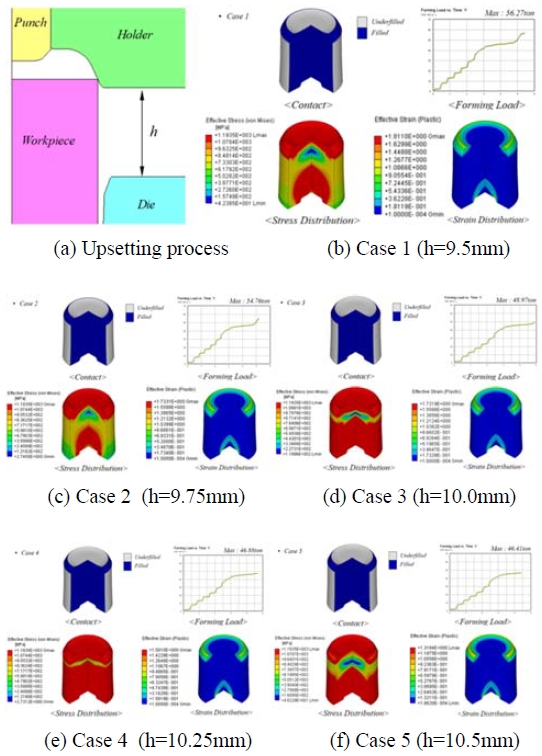
Simulation results for upsetting process
Reflecting the tolerance range of actual shop-floor press equipment, the level of height ‘h’ was established across five total levels: 9.50 mm (Case 1), 9.75 mm (Case 2), 10.00 mm (Case 3), 10.25 mm (Case 4), and 10.50 mm (Case 5), and subsequently implemented into the simulation models. The quantitative analysis results of the contact behavior, forming load, effective stress, and effective strain calculated for each process variable through the finite element analysis are depicted in Figure 5.
As a result of the analysis, h was 10.25 and 10.50 mm, and the load was the lowest. The stress was almost similar, and it can be seen that the strain tends to decrease slightly as the h value increases.
3.3 Near Net Shape Process for Pinion Gear
To achieve defect-free full-filling formation across the entire gear tooth profile without any subsequent machining in the combined multi-stage forging process, multifaceted plastic flow optimization analyses were conducted on the geometric internal dimensions of the die. Three parameters were derived as the core design variables for the optimization analysis such as the clearance between the die and the material, the upper corner fillet radius on the punch side, and the lower corner fillet radius on the die side (Figure 6). Figure 7 show the tools shapes.
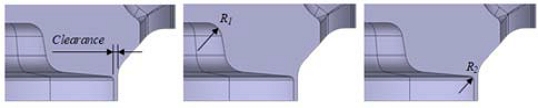
Design parameter for FE simulation
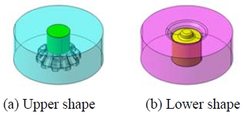
Punch and die shape in near net shape process
Considering the tolerance performance and structural strength of the shop-floor tool manufacturing, the levels for each variable were established across three levels: clearances of 0.4, 0.5, and 0.6 mm; punch-side R1 of 1.5, 2.0, and 2.5 mm; and die-side R2 of 0.5, 0.75, and 1.0 mm (Table 1). To enhance experimental efficiency and verify the independent effects of the design variables based on orthogonally, a total of nine representative finite element analysis (FEA) combination models were established using an orthogonal array, and the simulations were subsequently executed as shown in Table 2. To quantitatively identify un-filling defects of the tooth profile which are considered the most critical defect due to the nature of the combined forging process the minimum distance between the internal surface of the die cavity and the deformed material surface was defined as the objective function and tracked accordingly. The finite element analyses were carried out according to the orthogonal array, and the results are summarized in Figure 8 and Table 2.

Design parameters
OA table and results of simulations

FE simulation results according to OA table (Table 2)
Fundamentally, as the clearance increases, the metal flow resistance and forming load decrease due to the opening effect of the flash escape path within the die. However, in the excessive clearance region of 0.6 mm, the plastic pressure that should be directed toward the lowest section of the gear tooth profile was prematurely distributed and discharged, leading to severe un-filling defects at the bottom edge of the tooth. Conversely, when the clearance was set to 0.4 mm, the tooth profile filling was exceptionally well-controlled; however, the internal pressure required to flow the material escalated rapidly. This induced an excessive forming load that significantly exceeded the safe operating capacity of the 600-ton mechanical forging press designated for the actual mass-production line, rendering this condition unsuitable. Cross-sectional analysis of the simulation data revealed that the optimal condition that simultaneously satisfies the equipment's allowable load limits and ensures excellent die tooth profile filling was a clearance of 0.5 mm.
4. Optimization of Die Design for Pinion Gear
4.1 Optimization of Design Parameters
The analysis results from Table 2 were utilized as the input data for the ANN (Artificial Neural Network) to train the model and predict the objective functions for the unanalyzed design variables. The objective functions were defined as the minimum distance (clearance distance) and the effective stress values. For neural network training, combinations of design parameters (clearance, R1, R2) are used as inputs and the corresponding minimum distance are used as teacher signals. The structure of the network is an input layer, an output layer and two hidden layers having 10 and 5 neurons, respectively. The root mean square error is less than 10-7 and the iteration number of training cycles is 7850. The outputs obtained by network training show very good correlation with the results of FE-simulations.
After training, the optimal design variables were determined by setting the internal filling limit within the range of 0.55 mm to 0.60 mm, taking into account the geometric precision of the gear tooth profile. Following the neural network training, the clearance was fixed at 0.5 mm, and analysis graphs were derived by inputting R1 and R2 at a precise continuous variable scale of 0.01 mm. Figure 9 show the predicted results for minimum distance according to R1 and R2 using ANN. The complex computation results from the artificial neural network program demonstrated that as the lower fillet radius R2 and the upper fillet radius R1 increased, the plastic flow space at the tip of the tooth profile was gradually secured, causing the clearance distance—the objective function—to increase linearly. When considering only the clearance distance, the predicted optimal parameter combination was determined to be a clearance of 0.5 mm, R1 of 1.5 mm, and R2 of 0.5 mm. However, when taking stress into consideration, it was found that if the radius R1 (the internal flow space) was fixed too narrowly at the 1.5 mm level, non-uniform metal flow occurred at the localized shear cross-section inside the die cavity, leading to an increase in localized pressure. This phenomenon can induce fatigue damage to the die and cause premature failure of the tooth profile die during mass-production operations. Consequently, the optimal condition that simultaneously satisfies the multi-objective functions—namely, the distribution of forming loads, mitigation of localized stress concentration to enhance die tool life, and defect-free full-filling of the tooth profile—was predicted to be a clearance of 0.5 mm, R1 of 2.5 mm, and R2 of 0.5 mm.
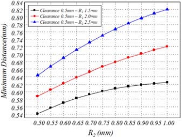
The predicted results of minimum distance by ANN
4.2 Field Test
Based on the forming analysis and neural network prediction results, a punch and die were produced by designing a clearance of 0.5mm, R1 of 2.5mm, and R2 of 0.5mm. It is shown in the prepared punch and die shape, Figure 10(a). And it is shown in the field test, Figure 10(b). After the final test, the shape of pinion gear after combined forging process is shown in Figure 10(c). The test results showed that a good product shape was obtained, and no defects such as un-filling cavity occurred.
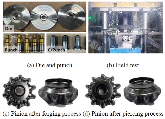
The test result of pinion gear in cold forging process
5. Conclusion
In this study, to achieve mass-production optimization and secure high-strength reliability for a pinion gear used in differentials—a core drivetrain control component of high-load hybrid mid-to-large SUVs—a streamlined three-stage near-net shape cold forging process design applying a combined forging-trimming die technology was developed, and its manufacturing feasibility was successfully validated, leading to the following conclusions:
- 1. A process simplification design that shortens the conventional four-stage forging-trimming manufacturing method into a single-stage combined press die structure was successfully completed. By integrating this with a near-net shape geometric modification, the flash discharge flow at the parting line of the upper and lower dies was stabilized, thereby fundamentally preventing the occurrence of un-filling defects.
- 2. The plastic deformation mechanisms of the material under boundary variables in the upsetting and near-net shape combined forging processes were quantitatively identified through finite element analysis (FEA). By training a neural network algorithm model with the acquired simulation database, the optimal integrated geometric dimension conditions that simultaneously satisfy the distribution of forming loads and the tooth profile filling were successfully clarified.
- 3. The shop-floor experimental results demonstrated that defect-free pinion gears could be successfully fabricated. It is anticipated that by establishing an interconnected automated transfer line infrastructure in the near future, the unit cycle time will be drastically shortened, thereby fully enabling high-volume mass production.
The finite element analysis and AI-coupled cold forging process design methodology established in this study will serve as a key standard role model for advancing the forming technology of highly challenging, complex-shaped automotive gear components based on its competitiveness.
Acknowledgments
This work was supported by Changshin University Research Fund of 2026-018
Author Contributions
Conceptualization, D. H. Kim; Methodology, D. H. Kim; Software, D. H. Kim; Formal Analysis, D. H. Kim; Investigation, D. H. Kim; Resources, D. H. Kim; Data Curation D. H. Kim; Writing-Original Draft Preparation, D. H. Kim; Writing-Review & Editing, D. H. Kim; Visualization, D. H. Kim; Supervision, D. H. Kim; Project Administration, D. H. Kim; Funding Acquisition, D. H. Kim.
References
- J. Zhou, Y. Wang, X. Zhang, and L. Huang, “Optimization of process parameters for warm forging near-net forming of driving pinion gears using FE simulation,” Journal of Materials Processing Technology, vol. 288, p. 116902, 2021.
- M. S. Khan, T. S. Lee, and J. H. Kim, “Three-dimensional finite element analysis of the multi-stage cold forging process for steering pinion shafts,” International Journal of Advanced Manufacturing Technology, vol. 112, no. 5, pp. 1435-1448, 2021.
- H. W. Lee, S. Y. Park, and Y. T. Cho, “Die design optimization for hot forging of wind turbine pinion shafts using DEFORM-3D and neural networks,” Metals, vol. 13, no. 4, p. 712, 2023.
-
N. Rajendran, C. C. Yurgel, W. Z. Misiolek, and R. Alves de Sousa, “Hot forging die design optimization using FEM analysis for near-net forming of 18CrNiMo7-6 steel pinion shaft,” Metals, vol. 13, no. 4, p. 815, 2023.
[https://doi.org/10.3390/met13040815]

-
J. G. Eom, S. W. Jung, and M. S. Joun, “Metal forming simulation with emphasis on metal flow lines and its applications,” Transactions of Materials Processing, vol. 22, no. 6, pp. 323-327, 2013 (in Korean).
[https://doi.org/10.5228/KSTP.2013.22.6.323]
-
D. H. Kim, J. M. Lee, and B. M. Kim, "Development of Piercing Technology for CVJ Cage with Thick and Uneven Piercing Holes," Materials Science Forum, vol. 773-774, pp. 95–103, 2013.
[https://doi.org/10.4028/www.scientific.net/MSF.773-774.95]
- D. H. Kim and B. M. Kim, "The Application of Neural Networks and Statistical Methods to Process Design in Metal Forming Processes," Key Engineering Materials, vol. 274, pp. 411–416, 2004
-
D. H. Kim "Evaluation of scorpion body formability by plastic lubrication surface treatment," Journal of Advanced Marine Engineering and Technology, vol. 49, no. 5, pp. 355-361, 2025.
[https://doi.org/10.5916/jamet.2025.49.5.355]