
Numerical analysis of combustion chamber temperature characteristics in a combined IGG-GCU system for 174K-class LNG carriers under MDO-NG mixed combustion conditions

Copyright © The Korean Society of Marine Engineering
This is an Open Access article distributed under the terms of the Creative Commons Attribution Non-Commercial License (http://creativecommons.org/licenses/by-nc/3.0), which permits unrestricted non-commercial use, distribution, and reproduction in any medium, provided the original work is properly cited.
Abstract
This study numerically investigates combustion characteristics and internal temperature distribution in an integrated inert gas generator–gas combustion unit system for 174K-class liquefied natural gas carriers under marine diesel oil–natural gas mixed-combustion conditions. In conventional liquefied natural gas carriers, boil-off gas disposal and cargo-tank inerting are generally performed by separate systems. The integrated concept combines these functions in a common combustion chamber to reduce installation space and simplify system arrangement. Transient thermal-flow simulations were conducted for three operating modes: marine diesel oil combustion, natural gas combustion, and simultaneous marine diesel oil–natural gas combustion. The instantaneous peak gas temperatures after ignition were 2,345°C, 1,984°C, and 2,295°C at 0.196 s, 0.210 s, and 0.186 s, respectively. The peak-time ordering was therefore Combined mode, IGG mode, and GCU mode. After approximately 3–4 s, the chamber gas temperature stabilized at about 1,100–1,300°C, 1,000–1,400°C, and 1,200–1,400°C, respectively. The temperature histories are interpreted as operating-mode responses rather than a normalized comparison of intrinsic fuel properties because the fuel and combustion-air conditions differ among the cases. The present study uses the single computational grid retained in the completed project analysis; accordingly, the short-duration localized peaks are used for comparative interpretation rather than as independently verified structural design temperatures. Additional mesh/time-step sensitivity, detailed solver-input documentation, experimental validation, and conjugate heat-transfer analysis will be addressed in subsequent validation research before quantitative structural-design application.
Keywords:
Inert gas generator, Gas combustion unit, Marine diesel oil, Natural gas, Temperature distribution1. Introduction
With increasingly stringent environmental regulations established by the International Maritime Organization (IMO) and the continued development of the LNG carrier market, there is a growing need for environmentally sustainable, highly efficient, and localized marine equipment.
This study focuses on the development of an integrated Combined IGG-GCU combustion system applicable to 174K-class LNG carriers. The proposed system combines the functions of a Gas Combustion Unit (GCU), used to dispose of BOG generated from LNG cargo tanks, and an Inert Gas Generator (IGG), used to generate inert gas for cargo tank and associated-system inerting.
For LNG carriers, the safety framework for cargo containment and cargo-related gas systems is governed primarily by the IGC Code, while the IGF Code provides requirements for ships using gas or other low-flashpoint fuels outside the scope covered by the IGC Code [1][2]. This regulatory distinction is relevant when defining the design basis and certification boundary of an integrated IGG-GCU system.
The system incorporates a dual-fuel burner capable of combusting both BOG/NG and Marine Diesel Oil (MDO) and an integrated control system. Hardware-in-the-Loop Simulation (HILS) is part of the broader system-development and control-verification program; however, HILS is not used in the CFD analysis presented in this paper and is therefore outside the scope of the present numerical study.
In conventional LNG carriers, the GCU and IGG are frequently installed as independent systems. Such arrangements may increase installation space, piping complexity, equipment weight, maintenance requirements, and control-system interfaces. An integrated Combined IGG-GCU system can potentially address these limitations by performing BOG disposal and inert-gas generation within a single combustion system.
However, integrating these functions introduces additional design challenges because liquid and gaseous fuels with different physical and combustion characteristics must be handled within the same combustion chamber. In particular, the fuel phase, mixing process, local air-fuel ratio, heat-release distribution, flame stabilization, chamber-wall thermal loading, and cooling performance can affect the transient thermal response. Therefore, numerical evaluation of temperature development and heat-transfer behavior is required before the integrated concept can be translated into a full-scale thermal and structural design [3].
Earlier CFD studies relevant to fire and combustion consequence analysis have examined hydrogen jet fires, LNG release scenarios, and fire/explosion events in complex environments [4]-[10]. More recent marine studies have focused directly on natural-gas/diesel dual-fuel combustion. Nyongesa et al. numerically examined natural-gas stratification in a low-pressure marine two-stroke dual-fuel engine, while Zhang et al. quantified the influence of pilot-diesel injection timing on flame development and combustion response [14][15]. Yang et al. analyzed multi-mode diesel/natural-gas combustion and emphasized the strong dependence of heat-release characteristics on natural-gas substitution and injection strategy [13]. Rochussen et al. demonstrated that operating strategy and engine calibration materially affect methane slip and GHG performance in marine dual-fuel vessels [16], and Xiang et al. used CFD to show that equivalence ratio, pilot timing, and NG mass are coupled design parameters in marine dual-fuel engine optimization [17]. These studies indicate that fuel chemistry, mixture preparation, equivalence ratio, and operating condition should be separated when interpreting temperature and heat-release trends.
The Eddy Dissipation Concept (EDC), originally developed for turbulent reacting flows, relates the overall combustion process to turbulent fine structures and turbulence–chemistry interaction [11]. FLACS-Fire applies EDC as its primary combustion treatment and the Discrete Transfer Method as a recommended radiation model [12]. Recent work by Thabari et al. showed that EDC formulation and finite-rate chemistry selection can materially affect predicted flame temperatures and local reaction rates, particularly when spatial resolution is insufficient [20]. Accordingly, the present EDC-based results are interpreted as engineering CFD outputs whose short-duration local peak temperatures require mesh/time-step sensitivity and validation before being treated as quantitative design temperatures.
The specific contribution of the present study differs from recent dual-fuel engine-cylinder studies in three respects. First, it evaluates an external common combustion chamber that integrates IGG inert-gas generation and GCU BOG-disposal functions for a 174K-class LNG-carrier application. Second, it compares three target system operating modes—MDO-only, NG-only, and simultaneous MDO–NG combustion—within the same chamber geometry. Third, it focuses on transient chamber gas-temperature development and the resulting implications and limitations for integrated thermal design and control. The objective is therefore not to establish an intrinsic fuel-to-fuel combustion ranking, but to provide a mode-specific numerical assessment for the Combined IGG-GCU concept.
2. System Design and Analysis Conditions
2.1 System Configuration
The system investigated in this study is a Combined IGG-GCU system designed for application to a 174K-class LNG carrier. The system integrates the GCU function for disposing of BOG generated from LNG cargo tanks with the IGG function required for inerting cargo tanks and associated piping systems.

Principal dimensions of the Combined IGG-GCU
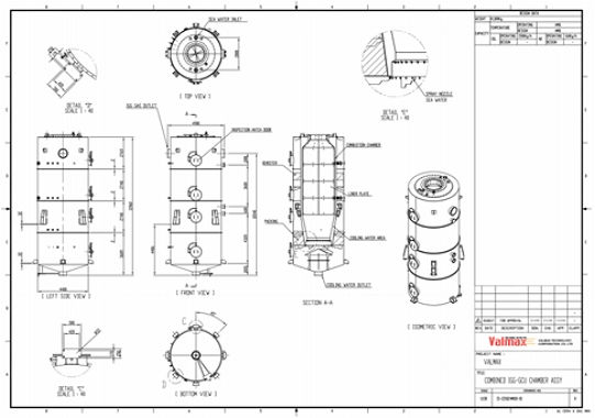
Design of Combined IGG-GCU
The major components of the system include a dual-fuel burner, combustion chamber, combustion-air supply system, fuel-supply system, cooling-water injection system, exhaust-gas discharge system, and integrated control system.
The dual-fuel burner is configured to operate with MDO and BOG/NG independently or simultaneously depending on the required operating mode. In IGG mode, MDO is used as the primary fuel to produce combustion gas with a low oxygen concentration for inerting purposes. In GCU mode, BOG/NG is combusted to control cargo-tank pressure. In Combined mode, MDO and NG are supplied simultaneously, allowing the common combustion chamber to accommodate both operating requirements.
Compared with independent GCU and IGG arrangements, the Combined IGG-GCU system may provide advantages in installation-space reduction, piping simplification, equipment-weight reduction, and integrated control. Because fuels with different physical and combustion properties are introduced into a common chamber, however, the effects of combustion rate, temperature distribution, wall thermal load, and cooling-water injection must be considered during the design process.
2.2 Simulation Conditions
Three numerical cases were established to compare combustion characteristics under different operating conditions. Case 1 represents IGG mode using MDO as the fuel, Case 2 represents GCU mode using NG as the fuel, and Case 3 represents Combined mode using MDO and NG simultaneously.
The same simplified combustion-chamber geometry was applied to all cases. The fuel-flow, combustion-air-flow, and heat-input values in Table 2 were taken from the system design specification for the target 174K-class Combined IGG-GCU system and represent the intended IGG, GCU, and Combined operating conditions. The archived thermal-analysis report separately records CFD fuel mass-flow rates of 1,500 kg/h for Case 1, 3,700 kg/h for Case 2, and 2,633 kg/h for Case 3. These operating modes were not generated by normalizing the cases to equal heat input or equal equivalence ratio. Accordingly, the present comparison represents mode-specific system behavior rather than a strictly normalized comparison of intrinsic fuel properties.
Principal system design conditions
The archived analysis was performed under transient conditions with a total simulation time of 30 s and a reported combustion duration of 10 s. Ambient temperature and pressure were specified as 25°C and 1 bar, respectively, and the atmospheric composition was assumed to consist of 79.05% nitrogen and 20.95% oxygen. The source report identifies the fuel release as a jet in the −Z direction. Detailed solver-level ignition-source energy/volume and internal activation timing are not available in the archived project record. Rather than reconstructing unverified values, these numerical-input details are treated as part of the follow-on validation work and will be explicitly defined and documented in subsequent simulations.
The reported temperature histories show ignition-related peak temperatures within approximately 0.1–0.2 s. This observed peak interval is reported as a simulation result and should not be interpreted as a separately documented ignition-input timing parameter.
The simulations were performed using FLACS-CFD v22.1r2. The k-ε turbulence model, Discrete Transfer Method radiation model, and Eddy Dissipation Concept combustion model were applied. For numerical simplification, MDO was represented by a dodecane-based surrogate, whereas NG was represented by methane, ethane, propane, and butane. Single-component or reduced surrogate fuels are widely used for engineering CFD because they reduce mechanism size, but validated multi-component marine-diesel surrogates have shown that surrogate composition can affect ignition delay, flame propagation, heat release, and emissions [18][19]. The present dodecane-based representation should therefore be regarded as a modeling simplification for comparative thermal-response analysis rather than a chemically complete representation of actual MDO. The cooling-water flow rate listed in Table 2 is a system design condition and was not explicitly coupled as a gas-wall-water heat-transfer boundary condition in the present CFD analysis.
The MDO and NG design heat inputs in Table 2 correspond to approximately 17.78 MW and 51.14 MW, respectively. The archived CFD case table gives a total fuel mass flow of 2,633 kg/h for Combined mode. This value is consistent with 1,500 kg/h of the MDO surrogate and approximately 1,133 kg/h of NG. Using the Case 2 NG heat input in proportion to the documented NG mass flow, the Combined-mode nominal thermal input is approximately 28.77×10^6 kcal/h (33.44 MW). The 4,700 m³/h NG value in Table 2 is retained as a system-design volumetric capacity; its reference temperature and pressure are not specified in the archived report and it is therefore not used to reconstruct the CFD mass flow. Likewise, the combustion-air values in Table 2 are retained as system design conditions because the archived CFD case table does not separately document case-specific FLACS air-inlet mass flows. Accordingly, a global AFR/equivalence ratio is not inferred from incomplete historical inputs in the present paper; a normalized analysis using explicitly defined fuel-composition and air-inlet bases will be addressed in subsequent research.
2.3 Theoretical Basis for Mixed-Fuel Thermal Response
The thermal response of a combustion chamber is determined not only by the nominal fuel heating value but also by the rate at which fuel and oxidizer mix, the local equivalence ratio, the spatial distribution of heat release, radiation from the flame and hot combustion products, convective transport, and heat removal through the chamber wall. For a multi-fuel system, the nominal chemical energy input can be expressed as the sum of the fuel mass-flow rates multiplied by their respective lower heating values [3].
| (1) |
The local combustion state is commonly characterized using the equivalence ratio, φ, defined as the actual fuel-to-air ratio divided by the stoichiometric fuel-to-air ratio. Values of φ below unity represent globally lean conditions, whereas values above unity represent globally rich conditions [3].
| (2) |
Because the operating cases use different fuel compositions, fuel-flow rates, and system design air-flow conditions, the resulting temperature histories reflect the combined effects of fuel type and operating condition. A direct conclusion that one fuel intrinsically produces a faster or hotter flame would require normalization by quantities such as total heat input, air-fuel ratio/equivalence ratio, burner momentum, and chamber residence time. The present paper therefore reports the available thermal-input and fuel-flow bases quantitatively and interprets the results primarily as a comparison among actual target operating modes. A fully normalized comparison, including explicitly defined AFR/equivalence ratio and burner/inlet conditions, will be incorporated in a subsequent validation study.
From a physical combustion perspective, gaseous NG is already in the vapor phase and can mix with combustion air without a liquid-fuel atomization and evaporation step. In an actual MDO burner, by contrast, liquid-fuel breakup, evaporation, and vapor-phase mixing contribute to the characteristic combustion time. This difference can contribute to a faster initial response for gaseous-fuel combustion; however, the present CFD model uses a simplified burner representation, so this theoretical interpretation should not be treated as a direct validation of the modeled flame mechanism [3].
In the EDC framework, turbulent reacting flow is represented through fine structures in which mixing and chemical reaction occur, and the rate of energy release is linked to the turbulence field and dissipation process [11]. Consequently, predicted temperature development depends on the modeled turbulence field as well as on the imposed fuel-release and ignition conditions. This point is important when interpreting the very short-duration temperature peaks immediately after ignition.
For thermal design, gas-phase flame temperature and metal-wall temperature must be distinguished. The instantaneous wall heat flux can be represented conceptually as the sum of convective and radiative contributions, while the heat removed by cooling water depends on the water mass-flow rate and temperature rise.
| (3) |
| (4) |
Accordingly, a high short-duration gas-phase temperature does not by itself establish the corresponding structural temperature or material limit. Quantitative structural assessment requires the time-dependent wall temperature, cooling-side boundary condition, wall thermal inertia, and thermal-stress response.
3. Numerical Analysis
3.1 Numerical Model
The combustion characteristics inside the Combined IGG-GCU combustion chamber were numerically investigated using FLACS-CFD v22.1r2. The actual Combined IGG-GCU geometry was simplified for numerical analysis and modeled within the FLACS environment.
FLACS (FLame ACceleration Simulator), developed by Gexcon, is a commercial CFD software package developed for process-safety applications and is used for fire, explosion, combustion, and gas-dispersion analysis. For fire simulations, the solver applies turbulence-combustion and radiation treatments suitable for consequence analysis in complex geometries [12].
FLACS solves the governing equations for compressible flow using a finite-volume approach on a three-dimensional Cartesian grid. Turbulent flow is modeled using Reynolds-Averaged Navier-Stokes equations together with the k-ε turbulence model. The present study uses the single computational grid retained in the completed project analysis, containing 450,776 cells with a minimum cell size of 0.099999 m and a maximum cell size of 0.404558 m. The modeled chamber corresponds to the principal chamber dimensions of approximately 4.9 m diameter and 12.0 m height. The source report also provides monitoring-point coordinates for MP1–MP27. Detailed solver time-step, convergence/residual, and ignition-source settings are not recoverable from the archived project report and will be explicitly defined and documented in the subsequent validation-stage simulations.
The single mesh described above is used consistently for the comparative assessment presented in this study. Because additional coarse/fine grid cases were not part of the completed project analysis, no mesh-independence claim is made in the present paper. Mesh and time-step sensitivity will be evaluated as part of subsequent validation research before the predicted local peak temperatures are applied quantitatively to structural-design verification.
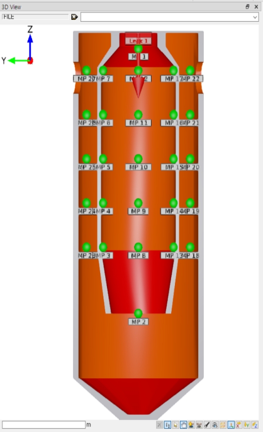
Simplified FLACS-CFD model and monitoring-point locations in the Combined IGG-GCU combustion chamber
3.2 Fuel Composition and General Numerical Conditions
The fuel compositions used for the three numerical cases are summarized in Table 3, while the principal operating flow rates are listed in Table 2. The general numerical conditions are summarized in Table 4. The values are retained from the source analysis dataset and the author-confirmed operating basis to preserve consistency with the original simulation results.
Fuel Composition for the Numerical Cases
General Numerical Conditions
The archived report lists the fuel-component entries as percentages but does not explicitly state the mass- or mole-fraction basis of the individual source-fuel compositions. The original percentages are therefore retained without assigning an unverified basis. The Case 3 composition can nevertheless be reproduced from the documented total fuel mass flow by combining 1,500 kg/h of the MDO surrogate with approximately 1,133 kg/h of NG (2,633 kg/h total) and applying mass-flow weighting to the reported source-stream percentage sets. Definitive confirmation of the individual source-fuel fraction basis will be included when the normalized fuel/air input set is re-established in the subsequent validation study.
3.3 Interpretation Scope of the Numerical Model
The present numerical model is intended to compare the transient thermal behavior of three operating modes using a common chamber geometry. It is not intended to reproduce every burner-scale phenomenon. In particular, the source model simplifies the detailed burner geometry and does not explicitly couple the cooling-water spray with the combustion-gas and chamber-wall heat-transfer fields. The cooling-water flow rate of 1,000 m³/h is therefore treated as a system design condition rather than a coupled CFD boundary condition.
The present analysis is based on the single computational grid retained from the completed project study and does not include a separate mesh-independence study, time-step sensitivity assessment, or direct experimental validation dataset. The documented mesh contains 450,776 cells with cell sizes ranging from 0.099999 to 0.404558 m. Because the principal numerical outputs include highly localized peaks occurring within approximately 0.2 s after ignition, the present paper limits these peak values to comparative interpretation and does not use them directly as structural design temperatures.
The additional verification needed for quantitative design use will be carried out in subsequent research. The planned validation scope includes multi-grid and time-step sensitivity, explicit documentation of the solver and ignition inputs, normalized fuel/air operating conditions, representative burner or prototype testing, and coupled gas-wall-water heat-transfer assessment.
4. Results and Discussion
4.1 Transient Temperature Response
The numerical results demonstrated that the temperature-rise and temperature-maintenance characteristics inside the combustion chamber differed among the three operating conditions. The phrase ‘fastest initial thermal response’ is not used here as a peak-time metric because the calculated peak times are 0.196 s for Case 1, 0.210 s for Case 2, and 0.186 s for Case 3. On the basis of peak occurrence alone, the order is therefore Case 3, Case 1, and Case 2. The NG-only case nevertheless shows earlier propagation of elevated temperature at selected downstream monitoring locations in the source histories; this transport behavior is treated separately from the peak-time metric.
Immediately after ignition, approximately between 0.1 and 0.2 s, the calculated temperature increased sharply and produced a local instantaneous maximum. The peak temperatures were 2,345°C at 0.196 s for Case 1, 1,984°C at 0.210 s for Case 2, and 2,295°C at 0.186 s for Case 3. These values correspond to short-duration local peaks immediately following ignition and should not be interpreted directly as continuous combustion-chamber wall temperatures.
During the initial 2–3 s combustion period, the internal monitoring-point temperatures were approximately 1,400–1,600°C for Case 1, 1,500–1,700°C for Case 2, and 1,400–1,600°C for Case 3. After the initial transient period, the combustion-chamber temperature tended to stabilize approximately 3–4 s after ignition. The quasi-steady temperature ranges were approximately 1,100–1,300°C for Case 1, 1,000–1,400°C for Case 2, and 1,200–1,400°C for Case 3.
Figure 6 compares the maximum gas-phase temperature histories for the three operating modes. The highest instantaneous peak occurs in Case 1, whereas the earliest reported peak occurs in Case 3. These two quantities therefore represent different response metrics and should not be combined into a single ‘fastest thermal response’ statement.
The high local temperatures calculated during the initial ignition period are partly associated with simplifications in the numerical representation of the burner. In the actual system, combustion is initiated at the burner and the combustion gases subsequently enter the main chamber. Because the detailed burner geometry and associated flame-development process were simplified in the present CFD model, the calculated instantaneous peak temperature may differ from the temperature experienced by the actual chamber wall.
Figures 3–5 present the temperature histories for the representative monitoring-point groups. MP3–MP12 correspond to locations inside the combustion chamber, whereas MP23–MP27 represent downstream locations outside the principal chamber region. The downstream histories are used primarily to compare trends because the cooling-water effect is not explicitly coupled in the present numerical model.
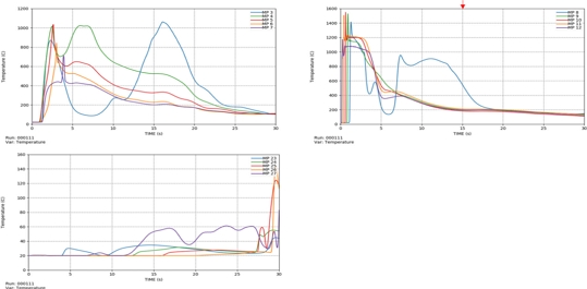
Temperature histories at representative monitoring points for Case 1 (IGG mode; Run 000111). MP3–MP12 are chamber monitoring points; MP23–MP27 are downstream points.
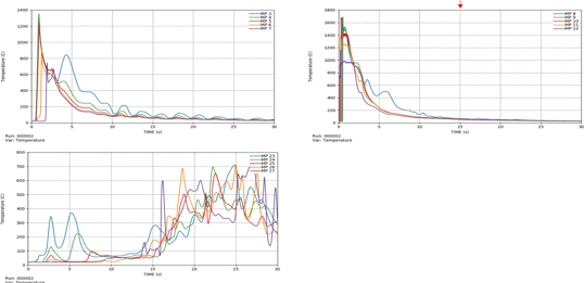
Temperature histories at representative monitoring points for Case 2 (GCU mode; Run 000002). MP3–MP12 are chamber monitoring points; MP23–MP27 are downstream points.
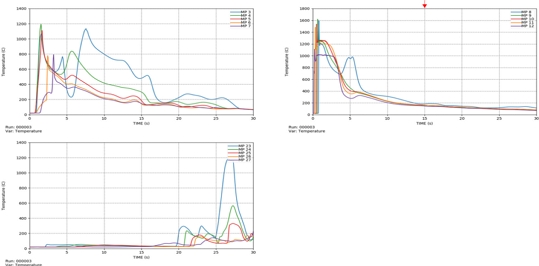
Temperature histories at representative monitoring points for Case 3 (Combined mode; Run 000003). MP3–MP12 are chamber monitoring points; MP23–MP27 are downstream points.
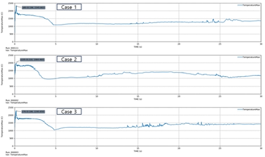
Time histories of the domain-maximum gas-phase temperature for Cases 1–3. The reported maxima are distinguished from individual monitoring-point temperatures.
Differences among the cases were also observed at monitoring locations downstream of the combustion chamber and were mainly associated with differences in combustion and hot-gas propagation. In the source monitoring histories, the NG-only case shows earlier arrival of elevated-temperature gas at selected downstream locations. This observation is used only as a qualitative propagation metric and is not interpreted as evidence that Case 2 has the earliest domain-wide peak temperature.
4.2 Interpretation of Fuel-Dependent Behavior
The NG-only case exhibits rapid temperature development and earlier hot-gas propagation at selected downstream monitoring locations. This behavior is qualitatively consistent with gaseous-fuel combustion, in which the fuel can mix with the oxidizer without the additional liquid-fuel atomization and evaporation processes required for MDO. However, the peak-time data show that Case 2 does not have the earliest instantaneous maximum; the reported peak times are 0.186 s for Case 3, 0.196 s for Case 1, and 0.210 s for Case 2. The gaseous-fuel explanation is therefore used only to interpret the observed propagation/mixing trend and not as a direct measurement of flame speed or chemical reaction rate [3].
The case-to-case temperature differences cannot be attributed solely to fuel chemistry because the operating conditions also differ in fuel flow rate and combustion-air flow rate. In other words, the present study compares three system operating modes, not three fuels under identical heat-release and equivalence-ratio conditions. This distinction is important because local flame temperature and transient heat release are affected by both fuel properties and operating parameters.
The highest instantaneous peak temperature was calculated in Case 1, while the earliest peak time occurred in Case 3. The NG-only case showed earlier downstream high-temperature propagation at selected monitoring points but a later domain-maximum peak time. These observations demonstrate that maximum temperature, peak occurrence time, and downstream propagation rate are separate metrics. Their differences can arise from the local mixture state, ignition treatment, heat-release concentration, and transport of hot products within the chamber.
4.3 Thermal Design Implications
For combustion-chamber design, the most relevant thermal quantities are the time-dependent wall heat flux, wall temperature, cooling-water heat removal, and resulting thermal stress rather than the gas-phase peak temperature alone. The calculated 1,984–2,345°C ignition peaks occur over a very short period and are localized gas-phase values. Their structural significance therefore depends on how much thermal energy is transferred to the wall during the transient event.
The source system includes a cooling-water design flow rate of 1,000 m³/h; however, the cooling effect is not explicitly coupled in the present CFD result. A simplified capacity estimate can nevertheless be made from Q̇cw = ṁcw·cp·ΔT. Taking water density as approximately 1,000 kg/m³ and cp as 4.18 kJ/(kg·K), 1,000 m³/h corresponds to approximately 277.8 kg/s and a sensible-heat capacity of about 1.16 MW per 1°C water-temperature rise. Thus, a 5°C and 10°C rise would correspond to approximately 5.8 MW and 11.6 MW, respectively. These values represent only theoretical cooling-water heat-removal capacity and are not the actual heat transferred in the present CFD model. Consequently, downstream gas temperatures remain comparative trends, and a conjugate heat-transfer model including combustion gas, SUS304 wall, and cooling water is required to determine wall-temperature distribution and actual cooling duty.
For SUS304, material adequacy should be evaluated using the predicted wall temperature and exposure duration together with the applicable allowable-stress and oxidation criteria. Direct comparison of the calculated flame or gas temperature with a material temperature limit would be overly conservative and physically incomplete because the wall has finite thermal inertia and is subject to convective, radiative, and cooling-side heat transfer.
From a system-design perspective, the Combined mode is of particular interest because it must maintain stable combustion while transitioning between liquid- and gas-fuel contributions. Therefore, future design verification should include turndown conditions, fuel-changeover transients, burner flame stability, oxygen concentration at the IGG outlet, exhaust-gas temperature control, cooling-water control range, and failure cases such as loss of one fuel or loss of cooling water.
4.4 Limitations and Future Validation
The present study has four principal scope limitations. First, the burner geometry is simplified, so burner-scale atomization, mixing, and flame anchoring are not fully represented. Second, the system design cooling-water flow rate of 1,000 m³/h is not explicitly coupled with gas and wall heat transfer. Third, the operating cases are not normalized to an identical total heat input or equivalence ratio, which limits fuel-only causal interpretation. Fourth, the completed project analysis uses one computational grid and does not include separate mesh/time-step sensitivity or direct experimental validation. These limitations are explicitly separated from the comparative temperature trends reported in this paper.
These unresolved validation items will be addressed in subsequent research rather than inferred from incomplete historical data. The planned follow-on work is: (1) re-establish and document the fuel-composition and CFD air-inlet basis for normalized AFR/equivalence-ratio comparison; (2) define and document the solver time-step, convergence criteria, and ignition conditions; (3) perform mesh and time-step sensitivity assessments; (4) introduce detailed burner geometry or a validated burner boundary condition; (5) couple cooling-water heat transfer to determine wall temperature; and (6) compare the CFD results with prototype or full-scale temperature measurements. This staged approach will extend the present single-grid comparative study into a quantitative chamber-design verification method.
5. Conclusions
First, the transient temperature response of the combustion chamber differed among the operating modes. The earliest reported instantaneous peak occurred in Combined mode (0.186 s), followed by IGG mode (0.196 s) and GCU mode (0.210 s). The NG-only case showed earlier hot-gas propagation at selected downstream monitoring locations, but this is a different metric from the domain-maximum peak time. The simultaneous MDO–NG condition therefore should not be characterized solely by an intermediate or faster/slower response without specifying the response criterion.
Second, the instantaneous maximum temperatures immediately after ignition were calculated to be 2,345°C in IGG mode, 1,984°C in GCU mode, and 2,295°C in Combined mode. Because these temperatures represent highly localized and short-duration transient gas-phase peaks, thermal safety should not be evaluated solely on the basis of these maximum values.
Third, approximately 3–4 s after ignition, the internal chamber temperatures tended to stabilize within approximately 1,100–1,300°C for IGG mode, 1,000–1,400°C for GCU mode, and 1,200–1,400°C for Combined mode. The actual chamber-wall and exhaust-gas temperatures are expected to differ from the predicted gas-phase combustion-zone temperatures and will be affected by the cooling-water system.
Fourth, the different temperature histories should be interpreted as operating-mode responses rather than as a fully normalized comparison of intrinsic fuel combustion properties because the cases use different fuel and air-flow conditions. The results nevertheless provide useful comparative information for chamber thermal design and control-strategy development.
Fifth, fuel composition, ignition-induced transient peak temperature, quasi-steady combustion temperature, wall heat transfer, and cooling-water performance should be considered together in the thermal design of a Combined IGG-GCU combustion chamber. Quantitative material and structural assessment requires wall-temperature and thermal-stress analysis rather than direct use of gas-phase peak temperature.
Finally, the present study provides basic numerical design data for development of an integrated Combined IGG-GCU system for LNG carriers. The current results are intentionally limited to comparative operating-mode assessment using the single grid retained from the completed project analysis. The remaining quantitative verification items—including normalized AFR/equivalence-ratio analysis, detailed solver-input documentation, mesh/time-step sensitivity, burner-scale or representative experimental validation, conjugate gas-wall-water heat-transfer analysis, prototype/full-scale temperature measurement, and thermal-stress assessment—will be addressed progressively in subsequent research before the CFD results are used for quantitative structural-design certification.
Nomenclature
| BOG : | Boil-Off Gas |
| MDO : | Marine Diesel Oil |
| NG : | Natural Gas |
| IGG : | Inert Gas Generator |
| GCU : | Gas Combustion Unit |
| LHV : | Lower Heating Value |
| ṁ : | Mass Flow Rate [kg/s or kg/h] |
| T : | Temperature [°C or K] |
| k : | Turbulent Kinetic Energy [m²/s²] |
| ε : | Turbulent Dissipation Rate [m²/s³] |
| CFD : | Computational Fluid Dynamics |
| RANS : | Reynolds-Averaged Navier-Stokes |
| φ : | Equivalence Ratio |
| q″ : | Heat Flux [W/m²] |
Acknowledgments
This work was supported by the Korea Planning & Evaluation Institute of Industrial Technology (KEIT) under the project “The Development of Combined GCU (Gas Combustion Unit)/IGG (Inert Gas Generator) System for 174-Class LNG Carrier” (Project No. 20017182).
Author Contributions
Conceptualization, D. H. Lee and B. R. Ryu; Methodology, D. H. Lee and J. W. Jung; Formal Analysis, D. H. Lee and J. W. Jung; Investigation, D. H. Lee and J. W. Jung; Resources, D. H. Lee and J. W. Jung; Data Curation, D. H. Lee and J. W. Jung; Writing—Original Draft Preparation, D. H. Lee; Writing—Review & Editing, D. H. Lee, B. R. Ryu and J. W. Jung; Visualization, D. H. Lee; Supervision, D. H. Lee; Project Administration, D. H. Lee; Funding Acquisition, D. H. Lee and B. R. Ryu.
References
- International Maritime Organization, International Code for the Construction and Equipment of Ships Carrying Liquefied Gases in Bulk (IGC Code), 2016 ed., London, UK: IMO, 2016.
- International Maritime Organization, International Code of Safety for Ships Using Gases or Other Low-flashpoint Fuels (IGF Code), Resolution MSC.391(95), London, UK: IMO, 2015.
- S. R. Turns and D. C. Haworth, An Introduction to Combustion: Concepts and Applications, 4th ed., New York, NY, USA: McGraw Hill, 2021.
- D. Muthusamy, O. R. Hansen, P. Middha, M. Royle, and D. Willoughby, “Modelling of hydrogen jet fires using CFD,” Proceedings of the 4th International Conference on Hydrogen Safety, San Francisco, CA, USA, Sep. 12–14, 2011.
-
T. Baalisampang, R. Abbassi, V. Garaniya, F. Khan, and M. Dadashzadeh, “Modelling an integrated impact of fire, explosion and combustion products during transitional events caused by an accidental release of LNG,” Process Safety and Environmental Protection, vol. 128, pp. 259–272, 2019.
[https://doi.org/10.1016/j.psep.2019.06.005]

- N. Pedersen, Modeling of Jet and Pool Fires and Validation of the Fire Model in the CFD Code FLACS, Master’s thesis, Department of Physics and Technology, University of Bergen, Bergen, Norway, 2012.
-
A. Al-Shanini, A. Ahmad, and F. Khan, “Accident modelling and analysis in process industries,” Journal of Loss Prevention in the Process Industries, vol. 32, pp. 319–334, 2014.
[https://doi.org/10.1016/j.jlp.2014.09.016]
-
M. J. Assael and K. E. Kakosimos, Fires, Explosions, and Toxic Gas Dispersions: Effects Calculation and Risk Analysis, 1st ed., Boca Raton, FL, USA: CRC Press, 2010.
[https://doi.org/10.1201/9781439826768]
-
G. Atkinson, E. Cowpe, J. Halliday, and D. Painter, “A review of very large vapour cloud explosions: Cloud formation and explosion severity,” Journal of Loss Prevention in the Process Industries, vol. 48, pp. 367–375, 2017.
[https://doi.org/10.1016/j.jlp.2017.03.021]
-
T. Baalisampang, R. Abbassi, V. Garaniya, F. Khan, and M. Dadashzadeh, “Review and analysis of fire and explosion accidents in maritime transportation,” Ocean Engineering, vol. 158, pp. 350–366, 2018.
[https://doi.org/10.1016/j.oceaneng.2018.04.022]
-
B. F. Magnussen and B. H. Hjertager, “On mathematical modeling of turbulent combustion with special emphasis on soot formation and combustion,” Symposium (International) on Combustion, vol. 16, no. 1, pp. 719–729, 1977.
[https://doi.org/10.1016/S0082-0784(77)80366-4]
- Gexcon AS, FLACS-CFD v22.1r2 User’s Manual, Bergen, Norway: Gexcon AS, 2022.
-
L. Yang, S. Ji, J. Hunicz, R. Wang, A. Zare, Y. Su, and D. Ji, “Analysis of multi-mode combustion and performance in a marine diesel/natural gas dual-fuel engine based on an irreversible equivalent combustion cycle theory,” Energy, vol. 326, 136248, 2025.
[https://doi.org/10.1016/j.energy.2025.136248]
-
A. J. Nyongesa, J. K. Kim, and W.-J. Lee, “Study on natural gas stratification enhancement in low-pressure natural gas-diesel dual-fuel marine two-stroke engine using CFD approach,” Journal of Advanced Marine Engineering and Technology, vol. 47, no. 6, pp. 303–308, 2023.
[https://doi.org/10.5916/jamet.2023.47.6.303]
-
X. Zhang, J. Gao, D. Fan, Q. Yang, F. Han, and H. Yu, “Impact of pilot diesel injection timing on performance and emission characteristics of marine natural gas/diesel dual-fuel engine,” Scientific Reports, vol. 14, 10713, 2024.
[https://doi.org/10.1038/s41598-024-61672-5]
-
J. Rochussen, N. S. B. Jaeger, H. Penner, A. Khan, and P. Kirchen, “Development and demonstration of strategies for GHG and methane slip reduction from dual-fuel natural gas coastal vessels,” Fuel, vol. 349, 128433, 2023.
[https://doi.org/10.1016/j.fuel.2023.128433]
-
L. Xiang, G. Theotokatos, and Y. Ding, “Parametric investigation on the performance-emissions trade-off and knocking occurrence of dual fuel engines using CFD,” Fuel, vol. 340, 127535, 2023.
[https://doi.org/10.1016/j.fuel.2023.127535]
-
P. Zhao, X. Sun, X. Liang, G. Jing, and T. Ma, “Development of multi-component surrogate fuel for marine diesel considering fuel physical-chemical properties,” Fuel, vol. 353, 129285, 2023.
[https://doi.org/10.1016/j.fuel.2023.129285]
-
X. Sun, M. Wang, A. Incecik, S. Feng, and Z. Li, “Development of a multi-component surrogate fuel model of marine diesel engine,” Ocean Engineering, vol. 233, 109022, 2021.
[https://doi.org/10.1016/j.oceaneng.2021.109022]
-
J. A. Thabari, G. Maragkos, A. Snegirev, and B. Merci, “Numerical study of the impact of the EDC formulation and finite-rate chemistry mechanisms in CFD simulations of fire plumes,” Fire Safety Journal, vol. 141, 103950, 2023.
[https://doi.org/10.1016/j.firesaf.2023.103950]